Figure 18: Plan view of the single suspended droplet furnace
The wires were coated by projecting vaporised silica (Silicone Fluid, by Dow Corning Corporation) from a Bunsen burner. Coating reduces catalytic action of the metal upon carbon residues, should they exist. Also, the thermocouple arm was earthed in order to eliminate electronic disturbances on the oscilloscope caused by the BBC computer that logs the combustion sequences. The combustion thermocouple, mounted on a silica support, was thus introduced in an electrically heated furnace.
The furnace is formed by three silica tubes, one main tube and two side arms sealed to the main tube in right angles. Dimensions are shown in Figure 18.
Heating was generated by a Kanthal coil placed around the main tube (see Figure 19), operated by means of a Sirect controller and a 10 amp. full-scale-deflection ammeter. The temperature in the furnace was controlled by a probe thermocouple inserted in the main tube at a long distance from the combustion thermocouple so that temperature variations due to convective streams were avoided. The furnace insulation was provided by Kaowool placed between the tubing and the case.
The light emitted by the burning samples was detected by a planar photodiode placed opposite the combustion thermocouple.
The droplet samples suspended on the combustion thermocouple were swiftly introduced into the furnace by a manually controlled stepping-motor. The temperature history registered by the combustion thermocouple and the light recorded by the planar photodiode were conveyed to and processed in a Gould Digital Storage Oscilloscope 4035, where combustion sequences lasting from 1 to 500 seconds can be stored. The signal was filtered to eliminate noise disturbances. Subsequently, the sequences were stored on a BBC Computer via an IEEE interface. Hard records of the combustion sequence were obtained by plotting the oscilloscope display by a Hewlett Packard 7475 A plotter.
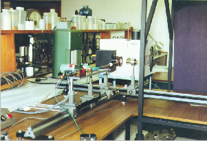
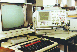
Figure 21: (from left to right) BBC computer, Gould processor, Gould oscilloscope and motor drive
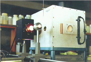
Figure 22: (from left to right) Light projector and single suspended droplet furnace
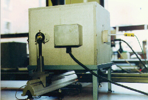
Figure 23: Photo-diode, furnace and control probe thermocouple
This diameter was used to establish correlations with the combustion parameters.
Fifteen valid runs were performed with every fuel at each furnace temperature attempted. The diameters of the droplets ranged from 0.4 mm to 1.2 mm. For droplets of 1 mm diameter the ratio of the volume occupied by the thermocouple wires to the total droplet volume is approximately 0.8 %, whereas for droplets of 0.5 mm diameter it approaches 3 %, and so it begins to be significant.
The low viscosity of the sample M2 did not allow the suspension of droplets at room temperature. In fact, this oil had to be cooled in ice prior to the experiments.
The furnace was flushed with air during 10 minutes prior to each experiment.
During the insertion process the sample is protected by a tubular silica shield, covered with aluminium foil, in order to prevent heat (mainly radiation) from the arm tube from reaching the droplet. The shield retracts in the later stages of the insertion process, allowing the sample to be exposed to the highest temperatures in the central part of the furnace.
The combustion parameters defined in the next paragraphs were correlated to the initial droplet diameter by means of the Least Linear Squares Method, according to the relationships proposed by Taylor and Burgess (Taylor and Burgess (1988)) . The vast majority of the regression coefficients proved good correlation between the initial droplet diameter and the combustion parameters (r2 > 0.85 at 600 °C furnace temperature and greater than 0.90 at higher temperatures).
In order to compare the performance of the fuels under study, calculations were made of the burning times for a standard droplet of 1 mm of initial diameter as obtained from the linear regressions. This diameter was chosen as data was available at this diameter from all fuels at all furnace temperatures. Although a smaller diameter would have been more representative of actual operating conditions, data availability was hampered by lack of ignition at low furnace temperatures (see section "4.6. Critical Diameter for Ignition").
Since none of the fuels studied exhibited a measurable formation of coke residue, no attempts were made to correlate the coke burn-out time with the initial droplet diameter.
 Previous |  Table of Contents |  Next |