4.3. Flame time (tf)
As in the Pre-ignition Delay three groups of behaviour can be differentiated.
Groups 1 and 2 show an increase of the Flame Time with the furnace temperature, their values rising to become nearly coincidental (Figure 28), although the increase is greater for Group 1 (fuels M2 and M3) than for Group 2 (fuels G4 and G5).
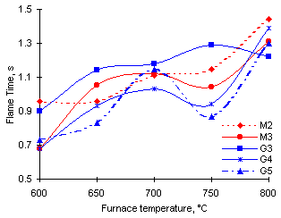
Figure 28: Calculated Flame Time for a standard 1 mm initial diameter droplet
However, the trend shown by Group 3 is that of a net increase in the values of tf, although at a lower rate than other groups. Finally the duration of its Flame Time decreases between 750 and 800 °C furnace temperature.
In general, the Flame Time increases with the furnace temperature. This can be explained in terms of the evaporation of fuel that takes place in order to form an ignitable mixture during the Pre-ignition Delay. At low furnace temperatures much fuel evaporates and diffuses into the surrounding air before an ignitable mixture is accomplished. Little mass of fuel is left in the droplet when ignition starts, and thus vaporisation and combustion of this remaining fuel take a shorter time to complete. As the furnace temperature rises the ignitable mixture is attained more rapidly, and the mass of fuel left in the droplet after ignition onset is large. Longer periods of time are required to vaporise and burn this fuel.
The trend observed is that of shorter Total Combustion Time for all fuels studied as the furnace temperature was increased. However, as a result of the behaviour of the flame stage both Groups 1 and 2 exhibit a net increase of the Total Combustion Time at 800 °C furnace temperature, which reverses the trend registered at lower furnace temperatures. Values of t are totally coincidental for oils of Group 2 (G4 and G5), similar to those of fuel M2, but values corresponding to M3 are lower within Group 1.
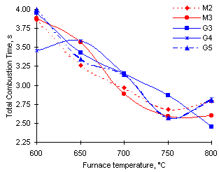
Figure 29: Calculated Total Combustion Time for a standard 1 mm initial diameter droplet
Group 3 (fuel G3) exhibits a distinct pattern of steady decrease of t values, thus becoming the sample with the shortest value of the Total Combustion Time at 800 °C.
Due to technical difficulties the Ignition Temperature could not be recorded adequately at furnace temperatures below 800 °C. Improvements in the equipment allowed its measurement at 800 °C with high accuracy. Most correlations performed yielded correlation coefficients (r2) greater than 0.85. One example is given in Figure 30.
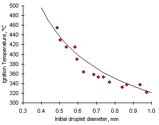
Figure 30: Graph showing the Ignition Temperature from experiments with fuel M3 at 800 °C vs do
The values of Ti are correlated to the inverse of the initial droplet diameter (Taylor and Burgess (1988)) according to:

Calculation of the Ignition Temperature for a standard 1 mm diameter droplet at 800 °C provided the values listed in Table 5:
| Fuel
| Ti, °C
|
| M2
| 314
|
| M3
| 321
|
| G3
| 359
|
| G4
| 364
|
| G5
| 367
|
Table 5: Ignition Temperatures of the samples studied at 800 °C furnace temperature
Clearly two types of behaviour can be distinguished: That of heavy coker gas oils (previously quoted as Group 1), their calculated Ignition Temperatures lying at about 318 ± 4 °C, and that of heavy vacuum gas oils (referred to as Groups 2 and 3), whose values of the calculated Ignition Temperature lie at about 363 ± 4 °C.
The experimental Critical Diameter for Ignition exhibits a decrease as the furnace temperature is increased in almost all cases (see Table 6). This is expected to occur as ignition of small droplets is achieved more easily at high furnace temperatures.
Although no clear trend of behaviour could be ascertained from the results obtained, at 800 °C the fuels of each given group show similar values of  .
.
| Fuel
| 600 °C
| 650 °C
| 700 °C
| 750 °C
| 800 °C
|
| M2
| 0.90
| 0.73
| 0.63
| 0.47
| 0.48
|
| M3
| 1.15
| 0.93
| 0.70
| 0.66
| 0.49
|
| G3
| 0.91
| 0.76
| 0.61
| 0.51
| 0.53
|
| G4
| 0.97
| 0.91
| 0.78
| 0.55
| 0.45
|
| G5
| 1.06
| 0.93
| 0.68
| 0.51
| 0.46
|
Table 6: Experimental values of the Critical Diameter for Ignition
Only one of the samples studied (M2) exhibits an appreciable increase of the droplet temperature after the extinction of the flame, especially at high furnace temperatures. The temperature of the droplets may reach up to 1,450 °C. Such a fact proves the existence of a solid residue on which heterogeneous reactions increase the temperature measured. Fuel M2 contains 0.10 % asphaltenes which is likely to form a small solid particulate.
In general, the tendency is that of increasing Peak Temperature for larger initial diameter and higher furnace temperature, although such pattern was not thoroughly obeyed in all experiments. Larger amounts of fuel give rise to higher heat release which is added to that stemming from the hot surrounding atmosphere.
A relationship between the Peak Temperature (Tc) and the initial droplet diameter can be ascertained from the experiments with fuel M2 at 700 °C. The relationship takes a quadratic form at 750 °C (Tc = 794 + 266 , r2 = 0.9249). It can be seen in Figure 31.
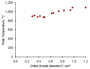
Figure 31: Relationship between the Peak Temperature and the square of the initial droplet diameter from experiments with fuel M2 at 750 °C
Other samples did not cause an increase of the Peak Temperature. In addition, visual observations did not reveal the appearance of solid residues except for fuel M2.
However, the combustion of all samples investigated is accompanied by the ejection of considerable amounts of soot. Soot emerges from the internal side of the flame, which agrees with observations previously made by other researchers (Law (1989)) . Its formation occurs as convective streams are established in the droplet centre at the onset of ignition, forming a fuel-rich zone that promotes soot formation. This effect is enhanced by the aromatic compounds contained in the fuels, which average 23.4 % for heavy vacuum gas oils (fuels G2, G3 and G4) and 32.9 % in heavy coker gas oils (fuels M2 and M3). The layer of soot particles is eventually expelled in the outward flow of the combustion gases. It settles on the thermocouple wires and burns out.
The basic combustion characteristics of five heavy gas oils have been investigated by the Single Suspended Droplet technique. The experimental results obtained confirmed that these fuels comply with most of the relationships established by Taylor and Burgess (Taylor and Burgess (1988)) for heavy oil droplet combustion.
Three groups of fuels with distinct combustion behaviours have been distinguished among the samples studied:
- Group 1: Includes fuels M2 and M3
- Group 2: Comprises fuels G4 and G5
- Group 3: Includes fuel G3.
The following conclusions can be drawn:
- As the furnace temperature rises up to 800 °C Group 3 (fuel G3) becomes the most easily ignitable sample, followed by Group 1 (M2 and M3) and Group 2 (fuels G4 and G5), the latter displaying the longest ti among the results obtained. The generic boiling ranges of the two groups of fuels suggest opposite behaviour, since heavy vacuum gas oils contain larger amounts of volatile matter which should assist rapid ignition.
- The Flame Time of Group 3 is also the shortest, as it shows a net decrease at 800 °C. However, Groups 1 and 2 experience an increase of tf up to similar values in experiments at 800 °C.
- As a result, Group 3 yields the shortest Total Combustion Time (t) at 800 °C, whereas both values of Group 2 are coincidental and intermediate between those of Group 1.
- The Ignition Temperature of Groups 2 and 3 (ie, all heavy vacuum gas oils) measured at 800 °C lie within the same range, approximately 363 ± 4 °C, which is higher than that of Group 1 (heavy coker gas oils) whose Ti lie at around 318 ± 4 °C.
- As expected the Critical Diameter for Ignition decreased as the furnace temperature was increased for all samples. However, this variable could not be correlated mathematically to any other parameter, possibly due to the inherent uncertainty of its measurement. At 800 °C furnace temperature the Critical Diameter for Ignition of all fuels converge to a narrow range of values at about 0.49 mm.
- Coke burn-out was present in experiments with fuel M2 only.
Pollutant formation and interaction in the combustion of heavy liquid fuels
Luis Javier Molero de Blas, PhD thesis, University of London, 1998
© Luis Javier Molero de Blas


