 ), as it reproduced various operating conditions. The predominant processes of pollutant formation vary with the equivalence ratio, which modifies the extent of the formation and disappearance of different compounds.
In this stage of the experimental work, two fuels of different nature and nitrogen and sulphur contents were selected to investigate the formation and emission of gaseous species. Three variables were significant in this work:
 ), as it reproduced various operating conditions. The predominant processes of pollutant formation vary with the equivalence ratio, which modifies the extent of the formation and disappearance of different compounds.
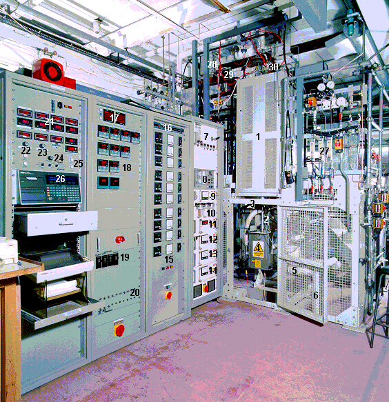
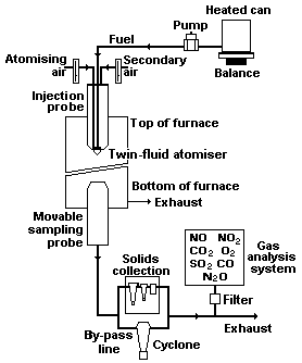
A photograph of the drop-tube furnace and its flow diagram can be seen in Figure 34 and Figure 35, respectively.
The combustion chamber is an electrically-heated, vertical ceramic cylinder, 8 cm in diameter and 1.3 m in height. The hot zone is about 1 m in length. It is heated by 44 Crusilite low voltage heating elements distributed in ten separate zones, which ensures isothermal operation in the furnace. The maximum furnace wall temperature is 1,200 °C, which is controlled by a Eurotherm 810 master programmable controller and nine Eurotherm 815 controllers. Type "R" thermocouples provide control, trip and data-logging functions.
The fuel is placed in a can, heated if necessary, which rests on a Sartorius 18100 P balance. The balance measures the weight of the fuel can and transmits it to an HP85 microcomputer every ten seconds. The computer calculates an 8-minute average of the fuel mass flow rate and relays the data to the Orion data-logger.
Various devices were used to pump the fuels. Initially a Gilson Minipump 3 was employed, this being subsequently replaced by a piston pump (see chapter VII for experiments with Orimulsion) and a Fluid Metering Inc. "Q" reciprocating pump (for non-emulsified-oils). Both were driven by a step motor. High flow rate stability was achieved by the latter two devices, which led to accurate readings with low standard deviation and simplifications in the data-handling software package.
The fuel lines of the injection system are fitted with heating devices and thermal insulation to enable the handling of fuels of high viscosity.
The fuel is sprayed downwards into the furnace through a coaxial external-mix twin-fluid atomiser formed by a fuel cap, air cap and retaining ring (see Figure 33). This atomiser assembly (manufactured by Spraying Systems Co.) produces a fine round spray with an angle of 21° and a length of 0.41 m at a pressure of 1.5 bar-g.


Figure 34: The drop-tube furnace. Below, description of numbered parts
| 1. Furnace | 16. Step-motor control |
| 2. Sampling probe | 17. Alarm panel |
| 3. Sampling probe step motor | 18. Press/temp controllers |
| 4. Solids collection box | 19. Over temperature trips |
| 5. Flue gas exit by-pass | 20. Heating switches |
| 6. Cyclones | 21. Press/temp indicators |
| 7. Heated filter and permapure assembly | 22. Atomising air controller |
| 8. NOX analyser | 23. Secondary air controller |
| 9. CO2 analyser | 24. Peristaltic pump controller |
| 10. Coalescers | 25. By-pass/solids-box switch |
| 11. O2 analyser | 26. Schlumberger data-logger |
| 12. SO2 analyser | 27. Cooling water flowmeters |
| 13. CO analyser | 28. Heated fuel can |
| 14. N2O analyser | 29. Pumps: peristaltic/piston/reciprocating |
| 15. Furnace current and temperature indicators | 30. Injection probe |

The fuel flows through the central orifice and is atomised by the flow of air which circulates between the fluid and air caps. Secondary air is directed around the air cap to establish the overall stoichiometry of the combustion environment. Atomising and secondary air mass flow rates are measured by Bronkhurst HI-TECH mass flow controllers.
The fuel and atomising air lines can be heated by a low voltage-high current supply. Firerod 50 W cartridge heaters facilitate steady temperature at the injection nozzle. Water circulates through the atomiser block to protect the nozzle from overheating from the flame and radiation from the furnace wall.
Sampling of combustion products is achieved by a water-cooled probe controlled by a step motor below the furnace duct. Its axial positioning in the furnace is achieved to a tolerance of ±0.5 mm.
If solid particulates are to be sampled, gases and solids are directed through two cyclones connected in series in the solids collection box, where most of the solid matter is removed for analysis.
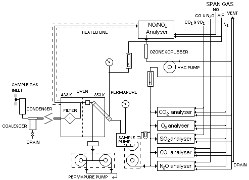
If solid particulates are not required, the exhaust gases are directed through a by-pass line and eventually into the facility reproduced in Figure 36 and described here:

The gas sample is split and it feeds both an NOX analyser and a Permapure drier, which uses compressed air to remove all remaining moisture. This latter sample line feeds all other gas analysers.
| NO | [NO] = 950 ppm / balance N2 |
| SO2/CO2 | [SO2] = 2,000 ppm / [CO2] = 14 % / balance N2 |
| CO/N2O | [CO] = 800 ppm / [N2O] = 80 ppm / balance N2 |
| NO2 | [NO2] = 40 ppm / balance N2 |
The rig was initially built at BP-Sunbury, and when transferred to UCL the gas exhaust system was modified. A main exhaust duct was fitted to direct the combustion gases to the main College extraction system. Also, a water-cooled drain pot was fitted in order to collect most condensables such as H2SO4, H2O. To provide better control of the condensing liquids and ensure their removal, thermocouples were fitted upstream and downstream from the drain pot. A low temperature on the downstream thermocouple implies correct water flow through the drain pot and elimination of condensables. Signals from both thermocouples are collected by the data-logger.
Data-logging is performed as follows. Sixty five channels send information from the rig onto a Schlumberger Orion 3531 D data-acquisition system. Such a system allows storage and replay of logged data. Data collection can be set at different time intervals, ranging from 15 seconds to 30 minutes. The data-logger is configured by a programme, "LOGGER1.CFG", which was modified to include new channels for monitoring of various temperatures, fuel line pressure, mass flow of dopant gases into the furnace and a counter of logs on the computer, among other changes.

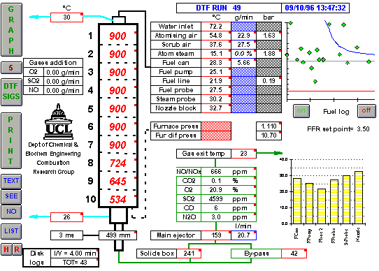
The data collected by the Orion data logger are sent via a General Purpose Interface Bus (GPIB) to a Zenith 486 PC computer. The computer handles the data by means of a specific Schlumberger software package named "AXIS". Data are finally presented on the screen in Microsoft EXCEL 4.0 spreadsheet format. Two spreadsheets were developed which present data updated every five seconds, namely "DTFSYS.XLS" (reproduced in Figure 37) and "DTFSIGS.XLS". Spreadsheet "DTFSYS.XLS" shows graphs for real-time monitoring of the weight measurements provided by the fuel balance and the temperature of various locations along the fuel injection lines. They provide better diagnosis of problems related to fuel flow, stability of measurements, validity of experiments, reliability of results, etc.
Data-handling was performed on a proprietary Excel 4.0 Macro, "ACTIGRA.XLM". This and its ancillary macros plotted the data out, performed statistical calculations and allowed other useful data-handling operations.
Finally, a "Manual of Operation" (Manual of operation of the UCL drop-tube furnace) was completed following instructions provided by the furnace manufacturer, Severn Furnaces plc, and its previous operator, British Petroleum plc. It complies with the characteristics of the equipment and its location at University College London.
 Previous |  Table of Contents |  Next |