This technique provides a better approach to real combustion conditions if compared to the single suspended droplet technique as the interference created by the supporting filament (heat transfer, nucleation, catalysis) is eliminated. However, even then the conditions created cannot match those of real combustion devices, as the effect caused by the simultaneous burning of adjacent droplets is not reproduced.
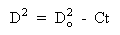
The changes in droplet size, flame evolution and other processes are observed, and they can be related to the combustion time. Bolt and Saad (Bolt and Saad (1957)) found that the diameter of droplets of light hydrocarbons followed the equation:
where:
D: droplet diameter at time t
Do: initial droplet diameter
C: coefficient of combustion
Experiments with n-heptane, iso-octane and kerosene revealed an increase of the mean velocity of the falling drops during the period of existence of the flame with respect to that of falling liquid spheres. Such an increase is due to a reduction of the drag force caused by mass transfer from the droplet to the surrounding atmosphere as a result of the flame.
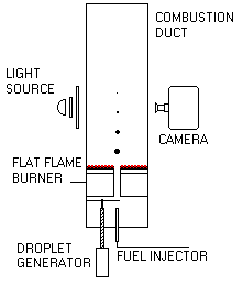
Malik and Burgess (Malik and Burgess (1985)) carried out experiments by forming droplets from an oil jet using a slotted disc. Droplets of sizes ranging from 175 µm to 800 µm travelled upwards in a laminar, oxidising environment produced by a methane/air flat flame. The results obtained showed shorter Pre-ignition Delays compared to those in the suspended droplet technique for a given droplet size (Malik and Burgess (1985)) , although also in linear relationship with the initial diameter. In addition to the increased mass transfer from the droplet because of its motion, the presence of active radicals originated in the auxiliary flat flame accelerated the ignition of the droplet, whilst in the suspended droplet the radicals are formed solely from the droplet. The Pre-ignition Delay also varied with the oxygen concentration in the post-combustion gases, showing that larger droplets need higher oxygen concentration to ignite.
Marrone et al. (Marrone et al. (1984)) generated droplets of heavy oils and some mixtures by a similar method to that of Malik and Burgess. It was observed in the photographic observations made that, although there was a considerable loss of mass, the droplet diameter remained constant, if not increase, throughout the droplet lifetime.
The study of the residues left after the combustion has also been undertaken by some researchers. Sampling of particles at different combustion stages by Marrone et al. (Marrone et al. (1984)) showed that a cenospheric structure is already formed before the flame is quenched after the burnout of the remaining volatiles. No. 2 fuel oil burned in a similar fashion to that of residual oils, although no coke particles were formed and little swelling was detected.
Urban and Dryer (Urban and Dryer (1990)) found that a parameter which they called the Coke Formation Index (CFI), relating the particle mass to the initial droplet mass, is constant for a given oil (see also section "4.4.3.a. Coke emissions"). They also established that this parameter related the physical characteristics of both the original droplet and the coke particle (Urban and Dryer (1990)) :
where:
Dc: coke particle diameter
Do: droplet diameter
 cs: coke shell density
o: oil density
 : coke shell thickness
 Previous |  Table of Contents |  Next |